
Getting Started with Atmel Studio – Blink
From the Arduino IDE to Atmel Studio
Everything that I needed to do could be done in the Arduino IDE. So why would I move to using Atmel Studio?
I recently finished up working through the edX course on Embedded Systems, and it showed me that I had a gap in my knowledge. I never really worked with registers, and didn’t do direct port manipulation – just because the Arduino IDE made it so easy that I never had to. The course also opened my eyes to the possibilities of debugging and simulating projects – including JTAG debugging.
So I thought, perhaps not with great maturity, that I need to “nerd up” and get started with a “real” tool.
I was also curious to learn what Atmel Studio offered beyond the Arduino IDE – given that it is developed by Atmel. Of course the “Hello World” of microcontrollers is the Blink sketch, so that’s where I started. It wasn’t that tough!
Choose your Programmer
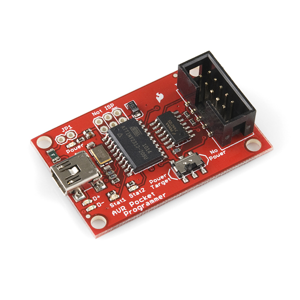
There are a number of programmers/debuggers that Atmel Studio natively supports. In addition to the official Atmel programmer and debuggers, there are a range sold by third parties. I won’t turn this post into a review of programmers, but will point you to a low-cost open-source programmer that I was using: the Pocket AVR programmer from Sparkfun (well, it’s actually based on the USBTinyISP, a collaborative effort). This doesn’t have built-in support in Atmel Studio, but more on that later.
Creating a Project with Atmel Studio
First up, you need to download Atmel Studio. I’m not going to hold your hand through this, it’s really straightforward.
Atmel Studio is hosted in the Visual Studio environment – some people hate Microsoft, but I cut my teeth on Visual Basic nearly 20 years ago so I was comfortable in the environment. Sure it may be a bit bulky, but I found the interface easy to work with and I love the autocomplete.

Create the project:
- Click File, New Project
- Choose GCC C Executable Project, and give the project a name and folder location. Click OK
- Select the device that the project will run on. You can search, or filter by family. For this case, I chose ATmega328P, and clicked OK
The project will now open with a skeleton code structure in place.

Before we write the code
Before we get stuck in, a little background work. Let’s make the LED blink on pin 13 – well, pin 13 if you’re working with an Arduino. Things in the microcontroller world are a little different. Take a look at the image below – this shows the mapping between the Arduino pin numbers and the “real” ones:

From this, you can see that pin 13 on the Arduino (in blue) is actually pin 19 on the ATmega328 chip. If you’re using the T-Board to build this project, then the pins are clearly numbered. However, to confuse you even further, Atmel Studio doesn’t even use the chip’s pin numbers – it uses ports.
The ATmega328 has 3 ports: PORTB, PORTC and PORTD. Each port has a number of pins (usually max of 8), labelled numerically. Eg. PORTB has 8 pins labelled PB0, PB1 … PB7. Looking at the diagram above, you can see that pin 19 is labelled PB5 – therefore it is on PORTB.
We won’t get into too much theory about port manipulation – there are great tutorials out there – but hopefully this will help you to understand the code a little better.
The Code
Finally! Type the following into the code window:
#include <avr/io.h>
#include <util/delay.h>
int main(void)
{
DDRB |= (1<<DDB5); //Set the 6th bit on PORTB (i.e. PB5) to 1 => output
while(1)
{
PORTB |= (1<<PORTB5); //Turn 6th bit on PORTB (i.e. PB5) to 1 => on
_delay_ms(1000); //Delay for 1000ms => 1 sec
PORTB &= ~(1<<PORTB5); //Turn 6th bit on PORTB (i.e. PB5) to 0 => off
_delay_ms(1000); //Delay for 1000ms => 1 sec
}
}
Compile the program
First, set this to a release version – on the toolbar, look for a drop-down box that may say “Debug”, “Release” or “Configuration Manager”. Select Release
Second, click on Build, Build solution (or press F7)
The program should compile – check for any errors in the message windows at the bottom of the screen.
Program the Microcontroller
If you’re using the Pocket AVR from Sparkfun or the USBTinyISP, then look here for notes on how to get going.
If not, then it’s pretty straightforward:
- Connect the ISP programmer to the ICSP header, and plug the USB cable into your PC
- Select the ISP Programmer that you will be using, by selecting the Project menu, then …properties
- On the Tool tab, select the debugger/programmer you’re using.
- Upload the program to the T-Board: Click on Debug menu, then Start without Debugging
- The LED should start blinking.
Congratulations! Let me know if you have any questions

I’ve just completed my brand new guide Arduino to AVR: Get Started in 3 Steps.
Get it now on Payhip for only $1.65.
Challenge yourself and learn how to gain the flexibility and additional control that the AVR microcontroller offers.
As a free bonus, get an ATmega328P pinout cheatsheet.
A few years ago I discovered that my programming skills could be used to make real-world things move and flash and beep - I haven't looked back since! I love sharing what I've learned along this pretty bumpy (but very exciting) journey into the world of embedded systems - and that's why this website exists. In addition to the website, I write a series for Nuts & Volts magazine that helps readers to move beyond the Arduino and into the world of AVR. I'm a dad with a couple of energetic youngsters and a really cool wife!