
Arduino Tutorial – Chapter 2.2: Components
Parts List

- 1 x Arduino UNO R3
- 1 x USB cable
- 1 x 330 Ohm resistor (R1)
- 1 x red LED (LED1)
- 2 x jumper leads
- 1 x breadboard
New Parts
Each time we come across a new part in our projects, I’ll quickly run through it with you. I’m not going to get too technical as we could end up losing ourselves in how the components work, rather than in how we use them. There is a detailed summary on each component in the reference sections at the back of the book.
New Part: Breadboard
I’m not going to crack any jokes about food – suffice to say that a breadboard has nothing to do with bread. A breadboard is an extremely useful way to prototype and test projects. It allows you to quickly and easily connect components together, and then remove them and re-use them for other projects. The alternative to a breadboard would be to use wires to connect your components together – a fiddly and lengthy process when you’re dealing with so many small components.
There are number of different types of breadboard, but they essentially work in the same way. Take a look at the image below:

To start with, you’ll see the board has a grid of small holes, just the right size to pop your component’s legs into. When you insert a component, springy contacts inside the board clamp onto them to hold them in place and ensure a good contact is made. These contacts are then connected to other holes on the board, allowing you to connect components together without using wires.
You’ll notice that the board is split into a number of sections – a power rail at the top and bottom, an upper section and a lower section. Each section connects the holes together differently:
Power Rail: All the holes in a single row (horizontally) are connected together – in the diagram above I’ve highlighted these in red and black. If you put a component in the top left hole, and another in the top right hole, they’ll be connected. If you put a component in row 1 and another in row 2, they won’t be connected. There are only 2 rows in the power rail – these are meant for the 5V (+) and GND (-) connections from the Arduino. You’ll see once we start building more complex circuits how useful it is to have 5V and GND connections along the length of the breadboard.
Upper and Lower Sections: In these, the holes are connected in columns (vertically) – I’ve shaded this in the diagram. All the holes in “A” above are connected, but they are not connected to the holes in “B”. The top and bottom sections are not connected together – they are split by the central divider and operate separately. So the holes in “A” are not connected to the holes in “C”, nor those in “B” to “D”. Again, you’ll soon get to see how useful this is later.
To insert a component into a breadboard, line the legs up with the holes and push gently. Some breadboards are tighter than others, and some component’s legs are weaker than others – it can help to use a pair of needle-nose pliers to push the leg into the breadboard. To remove a component, simply give it a gentle pull and it will come out ready for use in another circuit.
New Part: LED
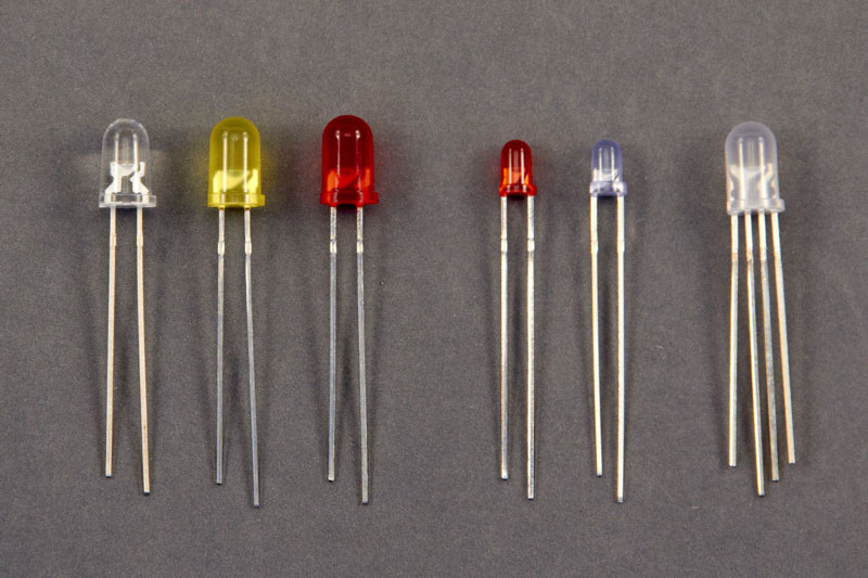
LED is an acronym for Light Emitting Diode – essentially a light source. They come in a variety of shapes, sizes, colours and brightness and are all around us – from dim “standby” lights on your TV, to torches, infra-red remote controls and cameras, and bright floodlights. In brief, they work by releasing photons (light particles) when electrons and electron holes combine. In the image above, we have a small sample of these – from left to right: white 5mm, yellow 5mm, red 5mm, red 3mm, blue 3mm, and RGB LED.
From their name, you can guess that LEDs are “diodes” – a semiconductor that only allows current to flow in one direction from the Anode (positive terminal) to the Cathode (negative terminal). The Anode and the Cathode are, for our purposes, the legs of the LED. As it’s a diode, LEDs will only light up if they are connected with the correct polarity. Another important affect, is that they’ll only complete the circuit and allow current to flow if they are connected to the right poles.
How do we know which is the Anode and the Cathode? Take a look at the image above (ignore the LED on the far-right for now) and see if you can spot a common design element. You probably noticed that one of the legs is longer than the other – this leg is the Anode. There is another difference which is easier to spot in larger LEDs – the LED casing is flattened on the side of the Cathode. Feel around the rim of the LED and you’ll notice a flat spot – not always very obvious, but it’s there.
The LED on the far right in the image above is an RGB variety. RGB stands for Red, Green, Blue, which hints that this special LED can output more than one colour. In fact, you can get close to reproducing the colours of the spectrum with this clever LED. These have four legs, three to control the amount of red, green and blue emitted, and a fourth which is either a common Cathode or Anode. When you buy these, you should be able to choose either a common Anode or common Cathode type – for our purposes common Cathode works best as it would be connected to GND.
Like all electrical components, LEDs are designed to handle specific current and voltages – exceed these and you’ll blow them (fortunately they don’t blow up in an explosion). For this reason, we always use a resistor with an LED in our circuits – a 330Ω resistor usually does the trick. Resistor? What’s that?
New Part: Resistor
Resistors are components that resist the flow of current – pretty well named, don’t you think! Let’s use a well-known analogy to explain how they work – that of pipes and water. Think of the current flowing in your circuit as water, and the wires as pipes in an irrigation system. Higher current equates to faster water flow. The problem with water flowing fast is that it can cause damage – say, blow your fine-mist sprinkler head off. To prevent this damage we need to slow the water down, and the easiest way to do this is by narrowing the pipe. That’s exactly what a resistor does – reduces the current flowing through it. Why do you need a lower current? To prevent a component being damaged (eg. the LED above), or because you don’t want it to shine as brightly, turn as fast, and so on.
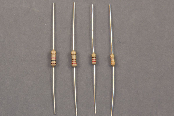
There are many types of resistor – fixed, variable, pressure-sensitive, light dependant… unless we specify otherwise we normally are referring to a fixed resistor – in other words one that has a fixed resistance to current. We measure this resistance in Ohms (Ω) – in the image above we have (left to right) a 1000Ω, 220Ω, 220Ω and 330Ω resistor. The resistance numbers can get big, into the millions, so we would normally refer to a 1,000Ω resistor as a 1k resistor (“k” is for the prefix “kilo”, meaning 1000). Similarly, a 1,000,000 resistor is called a 1m resistor (“m” standing for “mega”). For our projects we won’t use resistors below 100Ω.
How do we know a resistor’s rating? There isn’t really any space to print the resistance on these tiny components, so a system of colour-coding has been devised. The combination of the colour of the bands and their position allow you to calculate the resistance, with a terminal band showing the tolerance (or accuracy).
Unlike diodes, resistors are non-polar – they can be connected with either end to positive or ground.
Continue with Chapter 2: Schematic and Breadboard diagrams…