
Arduino Tutorial – Chapter 2.4: Breadboard Step by Step
Step by Step
This project is quite straightforward, so doesn’t really need step-by-step diagrams. However, I’ve been dying to do my first step-by-step so let’s do it anyway!
Step 1: Insert LED

Insert the legs of the LED into the breadboard. You should feel the legs stop when they hit the bottom of the board, and they should be held firmly by the contacts. The LED can still be wiggled around a bit. In the image above, the leg on the left is the anode, and the one on the right is the cathode (you can just see the flattened rim on the LED).
Step 2: Insert Resistor
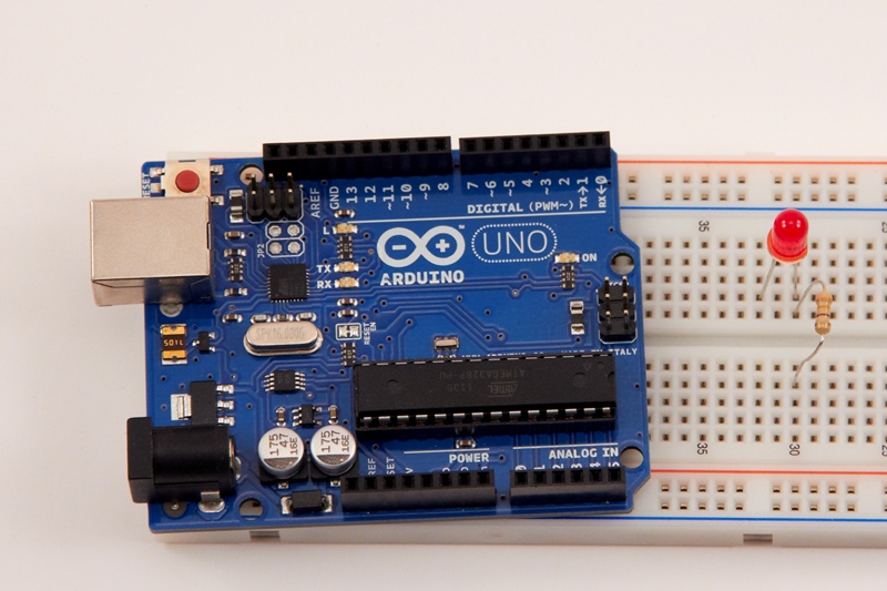
Insert the legs of the resistor into the breadboard. The resistor’s legs are usually not as strong as the LEDs, so you may need to use needle-nose pliers to gently push them into the board. Make sure that the one leg of the resistor is connected to the same column as the LED’s cathode, and that the other leg is on the other side of the breadboard divider.
Step 3: Connect GND
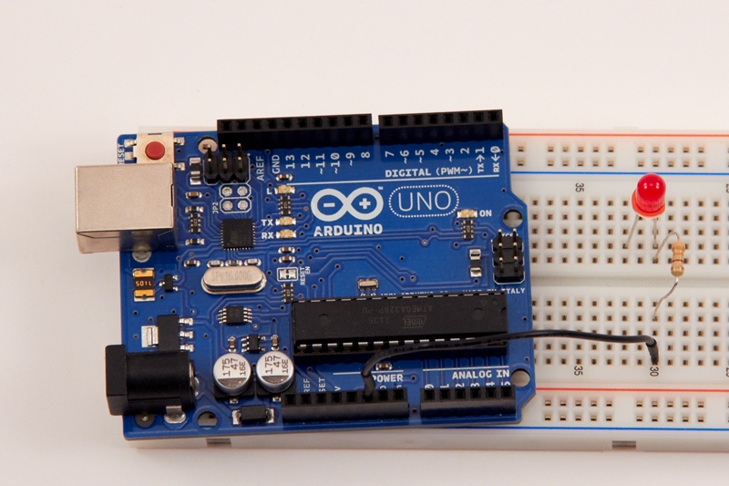
Connect one end of the black jumper wire to the GND pin on the Arduino – you’ll see that there are two GND pins, you can connect to either as they do the same thing. Insert the other end of the wire into the breadboard, in the same column as the resistor’s leg. As an aside, I’ve used a black jumper wire for the GND connection as it’s common convention to use black/blue for GND and red for positive power.
Step 4: Connect pin 13
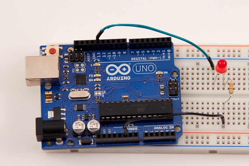
Insert one end of the green jumper wire into pin 13 on the Arduino, and the other end into the breadboard, in the same column as the LED’s anode.
Step 5: Connect USB Cable
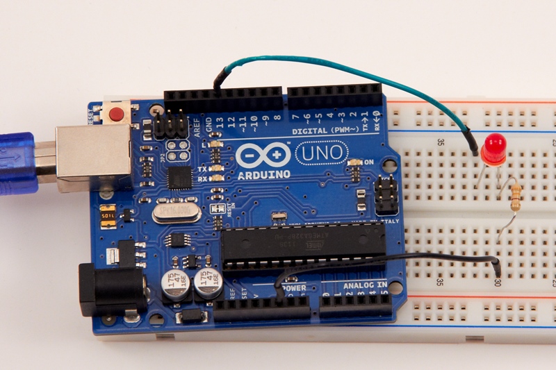
Congratulations – you’ve built the circuit! Now connect the USB cable to the Arduino. No need to plug it into your PC yet, as we still need to write the sketch (programme) to make the LED blink.