
Arduino Tutorial – Chapter 2.6: Your First Sketch
Programming the Blink Sketch
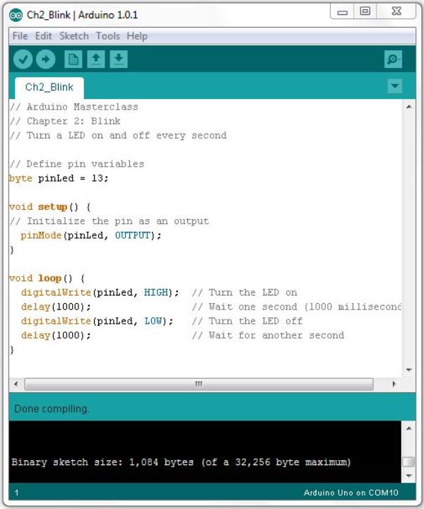
For now, type the sketch into the IDE as it’s set out below. You’ll need to copy it exactly – all punctuation is important, as well as the upper-and-lower case conventions used. Once you’ve typed the sketch in, we’ll look at the structure in a bit more detail.
Type the Sketch
// Turn a LED on and off every second
// Define pin variables
byte pinLed = 13;
void setup()
{
// Initialize the pin as an output
pinMode(pinLed, OUTPUT);
}
void loop()
{
digitalWrite(pinLed, HIGH); // Turn the LED on
delay(1000); // Wait one second (1000 milliseconds)
digitalWrite(pinLed, LOW); // Turn the LED off
delay(1000); // Wait for another second
}
Compile the Sketch
Once you’ve typed the sketch in, click on the “verify” button on the toolbar. If you’ve typed everything correctly, you should see a message “Done Compiling”:
Connect your Arduino
Now it’s time to connect your Arduino to your PC, using the USB cable. Make sure that you’ve already installed the drivers during the installation process detailed on the website. Plug the USB cable in, and you should notice the power LED on the Arduino light up. Wait a few seconds, then check that the correct board and port are selected:
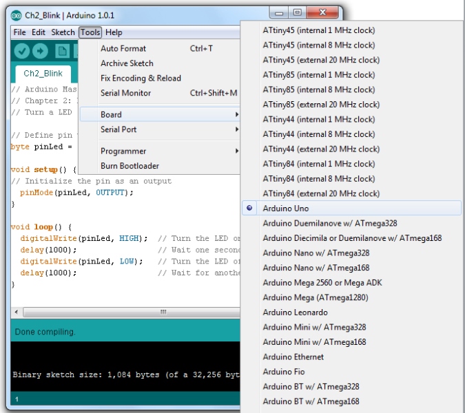
Select the Arduino Board: Click on the Tools menu, then Board, then select the Arduino board you’re using from the list
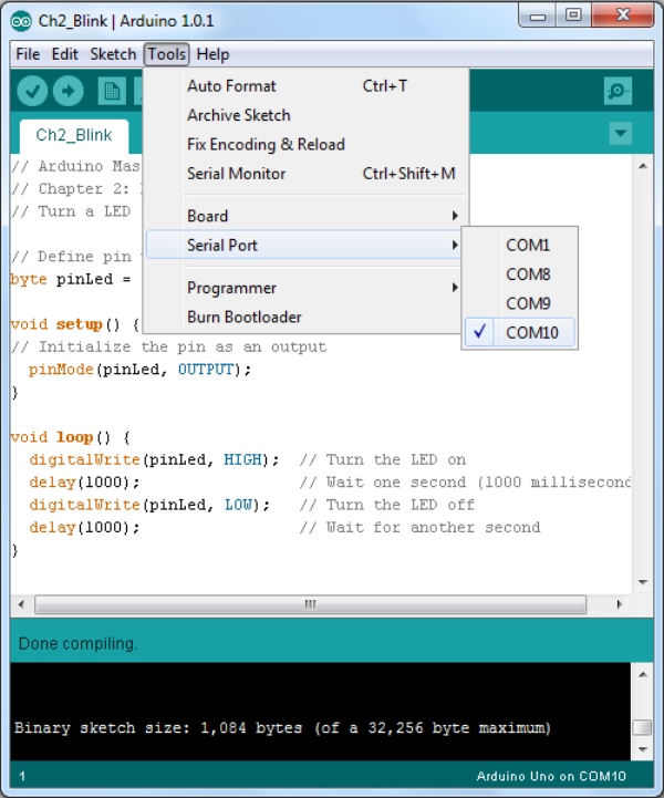
Select the Serial Port: Next, choose the serial port that your board is connected to by clicking on the Tools, Serial Port menu option. You would have identified the port during the driver installation process, but in case you ever forget try the following. First, disconnect your Arduino and wait 10 seconds. Click on the Tools, Serial Port menu and note down which ports are listed. Then reconnect your Arduino and wait 10 seconds. If you click on the Tools, Serial Port menu you should notice a new port appearing – this is your Arduino, so click on it.
Upload the Sketch
Now it’s time to upload the sketch to the board. Click on the Upload button on the toolbar, and watch the lights on your Arduino. First, the IDE should compile the sketch, then start uploading. As it uploads you should see your LED and some lights on the Arduino flash rapidly – these lights are the Tx and Rx (transmit and receive) which show the Arduino and the PC are communicating. After a while the lights will stop.
Blink!
You should now be seeing the LED on your breadboard steadily blinking on and off – on for one second, off for one second. Congratulations – you’ve just completed your first Arduino project!

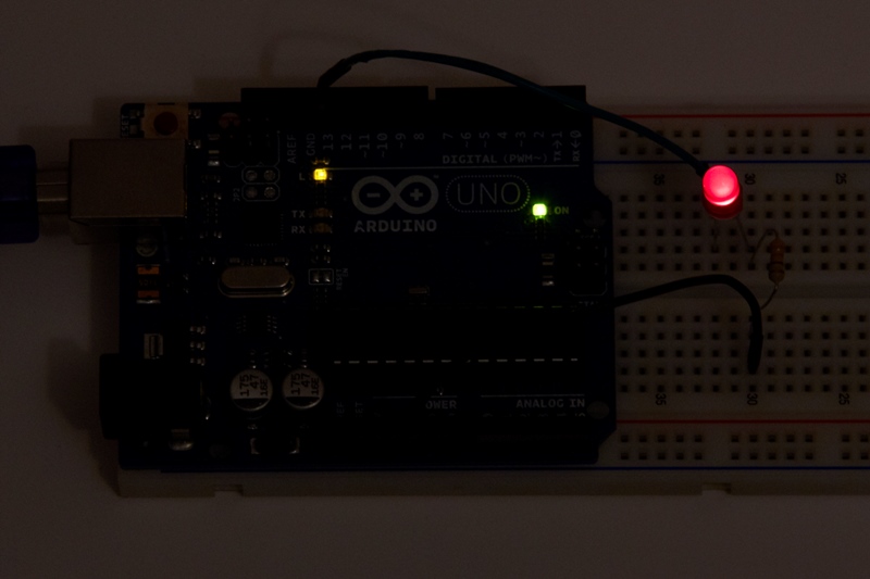
Did you notice that, in addition to your LED, there’s something else blinking? This is the Arduino’s on-board LED, which is permanently connected to pin 13. This is a useful feature – and one we’ll use in future projects – as you can use it to visually communicate things the Arduino is doing internally, without having to connect an additional external LED and resistor.