
Arduino Tutorial – Chapter 3.2: Traffic Light
The Traffic Light
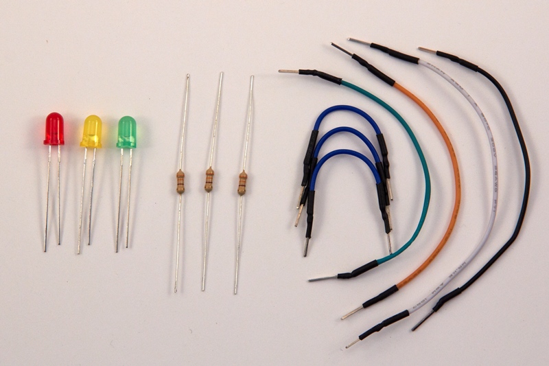
Parts List
From now on in, I won’t list the Breadboard, Arduino UNO R3 or the USB cable in the parts list as we’ll need them for every project we work on (that is, until we build our own Arduino board!).
- 3 x 330 Ohm resistor (R1,R2,R3)
- 1 x red LED (LED1)
- 1 x yellow LED (LED2)
- 1 x green LED (LED3)
- 4 x long jumper leads
- 3 x short jumper leads
Schematic Diagram
Before going on, I’d like to introduce 2 additional conventions, as they’ll help us to understand future schematics.
Supply Symbols and Junctions
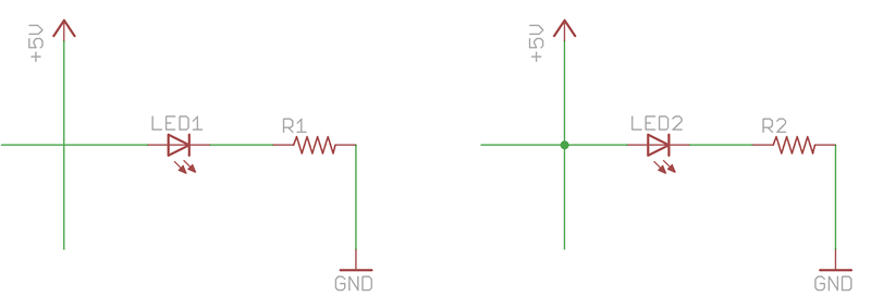
Supply Symbols: Take a look at the 2 circuits above. You’ll see that they both have an inverted “T” symbol labelled “GND”. Even though there is no wire between them, these two points are connected by virtue of their symbol and label. Similarly there are 2 arrows labelled “+5V” which are also connected even though there is no wire joining them. In complex circuit schematics, there will be wires running all over the diagram – by using these supply symbols, you can reduce the number of wires and therefore the clutter by replacing these common connections with symbols. The above diagrams are simple, so there is no real benefit to using them; as we move towards building our final project, you’ll see how useful this technique is in making circuits more easily readable.
Junctions: When drawing schematics, we should try to avoid (or minimise) wires crossing over one another – it makes them easier to read. However, as we get into more and more complex designs, we will need to draw wires crossing over other wires (without making a connection). Of course we also need some wires to make a connection. We therefore need a way to indicate whether a wire is connected to, or merely crossing over, another wire. As a standard, wires passing over each other are not connected unless there is a small dot at their intersection – this dot is called a junction. The circuits above look similar, and they both have crossing wires. However, the LED will only light up in one. Can you see which?
The LED will only light up in the circuit on the right. The LED in the left is not connected to the 5V supply as the wire supplying the 5V crosses over the wire running into the LED without making a connection. In the diagram on the right, there is a junction dot (i.e. a connection) on the 5V wire, which will result in 5V flowing into the LED.
Understanding the Traffic Light Schematic

With the above 2 concepts explained, the Traffic Light schematic should be easy to understand. The schematic is similar to the Blink schematic from chapter 2, except that we now have 3 LED’s and 3 resistors instead of 1.
Breadboard Diagram

The physical diagram should be fairly straightforward to understand. As we have multiple connections being made to GND (each resistor needs to connect to GND), we are making use of the power rail. The GND pin of the Arduino is connected to the ground power rail at the bottom of the breadboard – this then feeds each of the resistors. We’ll make more and more use of the power rails in future projects.
Step-by-Step
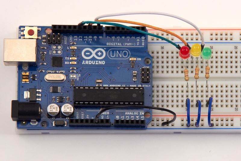
Given the similarity to the Blink project, let’s skip the step-by-step and simply take a look at the final circuit. Remember to connect the LED anodes to the 12, 10 and 8 pins, and the cathodes to the resistors and eventually GND.
The Sketch
The sketch is set out below:.
// Chapter 3: Traffic Light
// Light 3 LED’s in the following sequence:
// RED – 5 secs
// YELLOW + RED – 1 sec
// GREEN – 5 secs
// YELLOW – 1 sec
// Loop again
// Define pin variables
byte pinLedRed = 12;
byte pinLedYellow = 10;
byte pinLedGreen = 8;
void setup()
{
// Initialize the pins as output pins
pinMode(pinLedRed, OUTPUT);
pinMode(pinLedYellow, OUTPUT);
pinMode(pinLedGreen, OUTPUT);
}
void loop()
{
//Red signal
digitalWrite(pinLedRed, HIGH); // RED Light on
delay(5000); // 5 secs
//Yellow + Red
digitalWrite(pinLedYellow, HIGH); // YELLOW Light on
delay(1000); // 1 sec
//Green signal
digitalWrite(pinLedRed, LOW); // RED Light off
digitalWrite(pinLedYellow, LOW); // YELLOW Light off
digitalWrite(pinLedGreen, HIGH); // GREEN Light on
delay(5000); // 5 secs
//Yellow signal
digitalWrite(pinLedGreen, LOW); // GREEN Light off
digitalWrite(pinLedYellow, HIGH); // YELLOW Light on
delay(1000);
digitalWrite(pinLedYellow, LOW); // YELLOW Light off
}
Once you’ve entered the sketch, follow the same steps you did in for the Blink project – compile the sketch, and if it compiles successfully then upload it to the Arduino. If everything is connected correctly, and the upload is successful, you’ll see a traffic light on your breadboard.
Understanding the Sketch
To add a little more interest, I’ve chosen to write the sketch using the signal sequence in the UK and parts of Europe:
- Red: Stop
- Red + Yellow: Prepare to go
- Green: Proceed
- Yellow: Prepare to stop
The sketch should be very easy to understand, and serves to consolidate what we’ve learned so far.
Make a Few Changes
Challenge 3.1: Try using different value resistors (higher values than the 330Ω) on the three traffic light LEDs, and observe the impact that these have.
Challenge 3.2: Change the flash sequence from a UK/Europe sequence (red, red+yellow, green, yellow, red) to an international one (red, green, yellow, red).
Wrapping it up
After working through this chapter, you should feel more comfortable using the Arduino. It’s important to have the basics under control so that we can start heading into more challenging territory. We haven’t tackled anything very different, but have learned how to use loops to make sketches shorter and more efficient. We’ve also familiarised ourselves with a few conventions that apply to schematics.
Thanks a lot! it was very useful for my initial project, great!
Great, thanks for the comment pleased it helped!
Hello;
I am new in this field i need a simple single LED flasher/Solid circuit that accepts 3 types of input signal from a circuit one is positive +5v to gnd and other is -5v to gnd when +5 signal input to arduino it should solid ON and when -5v signal input the LED starts flashing LED at rate of 2sec and when no signal (below 2v) LED off.Please reply at faizan.hamayun@hotmail.com